My Engine design, torque monster, all imput welcome - Performance Forum

Forum Post / Reply
You must log in before you can post or reply to messages.
My Engine design, torque monster, all imput welcome
Tuesday, August 25, 2009 8:47 AM
Will use a LD9 for the basis of discussion.....
Stock LD9, VIN T motor
Engine Type Inline 4 Cylinder
Displacement 2.4 Liter (146 CID)
Bore: 90 mm 3.54 in
Stroke: 94 mm 3.70 in
Firing Order: 1-3-4-2
Horse Power: 150 @ 5600 rpm
Torque Rating: 155 @ 4400 rpm
Oil Pressure @ 3000 RPM 207 kPa 30 psi min.
Oil Pressure @ 900 RPM 69 kPa 10 psi min.
Fuel Delivery: Sequential fuel injection (SFI)
Thermostat opening temperature 180 degrees F

Rod and Piston Design
If you wanted a high revving high horsepower motor....
You would want a larger bore piston with a shorter stroke. The engine design would be made over square (cylinder bore is greater than stroke) to make it rev higher.

If you wanted a low revving high torque motor.....
You would want a smaller bore piston, with a long stroke. The engine design would be made under square (cylinder stroke is greater than the bore) to make it generate higher torque.

Our LD9 engines in stock form are designed to be more of a torque loving motor.

I have been thinking of this since Brad brought up longer rods. "Click Me"

ammfab wrote:i just googled stock stroke and rod length for the ld9. i found the rod length to be 5.710 (145.0mm) and the stroke to be 3.700 (94mm). then to find the rod stroke ratio (r/s ratio) u devide the rod length byt the stroke and get 1.54.

when u increase the rod length by lets say .300" to get a new rod length of 6.010 and then when u do th emath again u get a new r/s ratio of 1.62 which is better. it decreases side loading on the cylinder walls like the guys mentioned above which will free up some hp at the same time ur kepping the piston at TDC (dwell) for slightly longer also under the cylinder pressure from the combustion to give it a little more thrust on the way down............ u know what i mean.

as for the new pistons......... yeah u will need new ones with the pin bores moved further up on the piston. they should be moved the same amount as the rod length increase so that it lowers the pistons back down to the original postions, to prevent them from running into the head.

in the event that u have enough room between the head and pistons after u put long rods in and u opt not to run new pistons (because u have enough room), i dont think it will effect the compression ratio at all becaue ur engine is still drawing in the same amount of air as before and the piston dome hasnt changed any. compression ration is changed by the piston dome not putting a longer rod or bigger stroke in.

mike


DaFlyinSkwirl (PJ) - APU wrote:want to know what the skwirl has been up to? I've been doing a lot of homework for this coming year, deciding where I should take the skwirl next. A lot of you will be pleased to know that I plan on staying in the all motor category and mixing it up with ben for another year, and possibly section 8 cav with the 2.6 liter twin cam.

I am doing bottom end modifications this year, but a lot of people may be wondering whats going on... I've been doing TONS of homework the past 6 months, and have finally come to a decision. A lot of people may think I'm trying to accomplish a 2.4 ecotec swap.. and rational thought would agree.. no replacement for displacement right? well I'm going a route that some may think is a bit crazy... but take a look at this article and it may give you a slight idea as to my thought process:

ignore that this is from honda magazine.. those who are savvy know that if you're looking to copy/learn anything for all motor 4 bangers... honda is the company and aftermarket to look at for tips/tricks.


Rod/Stroke Ratio - What's Your Angle?
Dip into the intricate world of internal engine geometry and look closely at something you know very little about: rod/stroke ratios. (C'mon, admit it!) Editor Bob demystifies.
writer: Bob Hernandez


If there's one truth about Honda engines, it's that they like to scream. And Honda enthusiasts like to make them scream. The numbers on the tach reach so high, Honda practically offers the license: Go ahead. Make it sing. It's good at it. So long as you don't miss a shift, all is bliss.

Lightweight components, stronger materials and shorter strokes enable modern four-cylinder engines to spin very fast, yet last longer than ever. A tremendous amount of science goes into engineering and creating these high-spinning machines, most of it rooted in elementary principles of physics and geometry-fundamentals anyone planning to build an engine should know.

Understanding rod/stroke ratio, or the amount that a rod deviates from an imaginary straight line extending from the center of the crank journal to the center of the piston, is key to knowing how these machines deliver power at high rpm.

Determining the Rod/Stroke Ratio
To determine a motor's rod/stroke ratio, divide rod length (distance in millimeters from the center of the big and small ends) by stroke. A B18C1, for example, combines 138mm rods with an 87.2mm stroke for a 1.58:1 ratio.

Most engine builders shoot for a ratio between 1.5:1 and 1.8:1 on a street motor, with 1.75:1 considered ideal, regardless of application. (The most highly developed four-stroke engines in the world-F1 and motorcycle engines-have rod ratios of more than 2:1.)

The rod/stroke ratio affects several engine dynamics, including piston speed and acceleration, piston dwell at top dead center and bottom dead center, piston side loads, cylinder loading and bearing loads. Many of these elements play roles in engine aspiration, combustion and wear.

Generally, a lower ratio means a high rod angle, creating greater potential for accelerated wear to cylinder walls, pistons and rings. A low enough ratio, due to the severity of its rod angle, can drive a piston right into the cylinder wall.

Higher ratio engines, on the other hand, don't have the same friction concerns, but compromise in other areas. Air does not fill the intake ports with the same velocity, and there is less demand for the ports to flow as well since there is more time to fill and scavenge the cylinder (we discuss this phenomenon later). This typically means stagnant airflow at low revs and weaker torque. Hey, you can't have it all.

Lower Ratios-A Honda Characteristic
As the chart on this page indicates, many Honda ratios-designed for economy-fall on the low side. Honda produces compact, short four-cylinder engine blocks that don't require long rods. Most Honda blocks also feature a small bore. When coupled with a short stroke, the rod angle is still harsh, though not as bad as if the piston were larger in diameter.

Some tuners take the geometry into their own hands with longer rods. A longer rod makes more torque with the same piston force, and since it's less angular than a shorter rod, reduces sidewall loading and decreases friction. All of this adds up to more power.

Longer rods also give the pistons more "dwell," the brief periods of time the piston is at top dead center and bottom dead center. A longer dwell allows for better flow of intake and exhaust gases since the piston moves slower between up- and downstrokes.

Longer dwell also offers more time to fill the cylinders during the intake stroke and more time to scavenge during overlap. And since the piston hangs out at or near TDC longer, the combustion stroke has more time to deliver a thorough release of energy on to the piston.

In a stroked motor, the piston ultimately reaches greater speeds to cover the additional stroke. The speed makes intake, compression and exhaust strokes more turbulent and, consequently, more powerful. It also comes with its price in component wear, something to consider when looking into parts that increase stroke.

With a short stroke and a long rod, however, the piston accelerates more gently from TDC. It picks up its greatest speed further down the bore, at the point where the crank pin relative to the rod angle reaches 90 degrees. Since the pistons move from TDC slower, the entire bottom end absorbs less mechanical stress.

Advancing Toward A Thin Line
Even the short-stroke/long-rod combo has its limits. To accommodate extra rod length, some builders will move the piston pin higher into the slug, or opt for a deck plate. Either method requires an experienced wrench with access to a lot of custom parts.

Longer rods in a stroked motor can act to offset any increase in rod angle, but also requires a shorter piston. The deeper you dig into a piston to shorten it, the greater your odds of cutting into the oil ring groove and wreaking havoc with oil consumption. Most piston companies in the sport compact market engineer pistons with tighter ring packs and bridge rings to help avoid this problem.

Regardless of whether you take the stroker route or just run longer rods, you reach a point where you can no longer shorten a piston any further without compromising dependability.

Friendly Advice
Most engine builders believe longer rods are better, but a fringe of enthusiasts still dig the low-rpm torque that shorter rods can make. We advise builders who want a ratio of less than 1.6:1 to use the strongest aftermarket rods they can find, given the angle. We also recommend aftermarket sleeves to better fend off the lateral stress created by the rod angle.

Here's one last nugget to impress your friends with: a formula for calculating piston speed in feet or meters per second. The equation illustrates the point that the longer the stroke, the faster the piston travels at the same rpm.

Take a B16A2 vs. an H23. At 7000 rpm, the B16 slug moves 18 m/sec. At the same rpm, the H23 piston hauls additional ass-22 m/sec. Simply multiply stroke by rpm, and voil-minutes of endless doodling in class.

Stock Rod/Stroke Ratio Information For Some Popular Honda Engines
Block Rod length Stroke Rod ratio
D16A6, Z6, Y7, Y8 137mm 90mm 1.52:1
B16A1, A2, A3 134.4mm 77.4mm 1.74:1
B17A1 131.9mm 81.4mm 1.62:1
B18A1, B1, B20B4 137mm 89mm 1.54:1
B18C1, C5 138mm 87.2mm 1.58:1
H22A1 143mm 90.7mm 1.58:1
H23A1, A4 141.5mm 95mm 1.49:1
K20A, A2 139mm 86mm 1.62:1
K24A 152mm 99mm 1.54:1

by comparison:
block stroke rod ratio
L61 94.6mm 141mm 1.5:1
LSJ 86mm 144.84mm 1.68:1
LNF 86mm 144.84mm 1.68:1
LE5 99mm 143.7mm 1.45:1


you'll notice that the LSJ and the LNF have almost ideal r/s ratios.. (their r/s ratio is actually identical to the small block 350)

they're also very close to the K20A, and the K20A2.. which is starting to become a favorite amongst all motor honda enthusiasts, rivaling the B16A1/A2/A3 series in popularity

you can clearly see, since I'm looking for high rpm stability, top end breathing and less mechanical stress.. my bottom end selection is obvious

So my idea is to make an engine that is a torque monster with a stroke to rod ration as close to 1.75:1 as possible.

Pistons in my opinion need to be high compression. 10 or 12:1. Slightly decking the head, and using the 96-98 head or maybe even a 086 head seems like a great choice.


Header design.....
My ideal header in my opinion will be a 4-2-1 header with cylinder 1& 3 and 2 & 4 running together. With short, smaller diameter collectors, long primaries which should give me more power in the low to mid range rpm's, and also keep torque up high.


Exhaust design....
It seems that 2.25 to 2.5" piping from the header back seems to be my best bet. Since i will probably keep my stock rev limiter, and I shouldn't be pushing a lot of air, or revving to hell and back. I WILL be using a nice highflow cat.


Cam Design....
After talking to a few cam people they recommend something around....
240-260 degrees @ .050" with .375" for the intake
260-280 degrees @ .050" with .375" for the exhaust

but for some reason my brain keeps saying something around
215 degrees @ .050” with .360” lift for the intake
215 degrees @ .050” with .360” lift for the exhaust

Any help would be great!


Intake design
Longer thin runners seem to be better for lower to mid range power.
The plenum is where I can not get any kind of consistency. Some calculating say a Larger than stock plenum, and others say smaller than stock.....I'm kinda lost on plenum design. Design wise for low to mid range power stock sized or slightly smaller seems like a good route. but I'm VERY open to opinions.
56mm TB seems to be the sweet spot from my calculations. .....I could be way OFF.


Misc
Personally I do not believe I need a 2.3l oil pump conversion since I plan to not rev any higher than stock. I still might though, since the removal of the balance shafts seem like a great hp gain. Any questions concerns or anything please feel free to ask. The most questions the better.


PRND321 Till I DIE
Old Motor: 160whp & 152ft/lbs, 1/4 Mile 15.4 @88.2
M45 + LD9 + 4T40-E, GO GO GO

Re: My Engine design, torque monster, all imput welcome
Tuesday, August 25, 2009 8:57 AM
WOW!!! Good luck man


Re: My Engine design, torque monster, all imput welcome
Tuesday, August 25, 2009 9:17 AM
sounds interesting, I will keep watch


LE61T PTE6262 Powered

Re: My Engine design, torque monster, all imput welcome
Tuesday, August 25, 2009 9:49 AM
So do you have a defined numerical goal, or just go all out and see what it does? 180-200 ft/lbs should be obtainable.

I totally respect that you want an N/A torque monster, but if you really want a torque monster, grab a small-ish turbo (like gt28, t3, ect.), and multi-stage electronic boost controller and run high boost from the threshold to ~ 4500rpm and taper down to redline. This is how a stock LNF can make 400 ft/lbs @ 3000rpm safely. However the powerband will be low rpm and relatively narrow (think 2500-5000rpm); power will drop off bit time @ high rpm.


Re: My Engine design, torque monster, all imput welcome
Tuesday, August 25, 2009 9:51 AM
Sweeet.

Build it up


Re: My Engine design, torque monster, all imput welcome
Tuesday, August 25, 2009 10:55 AM
oldskool wrote:So do you have a defined numerical goal, or just go all out and see what it does? 180-200 ft/lbs should be obtainable.

I totally respect that you want an N/A torque monster, but if you really want a torque monster, grab a small-ish turbo (like gt28, t3, ect.), and multi-stage electronic boost controller and run high boost from the threshold to ~ 4500rpm and taper down to redline. This is how a stock LNF can make 400 ft/lbs @ 3000rpm safely. However the powerband will be low rpm and relatively narrow (think 2500-5000rpm); power will drop off bit time @ high rpm.

I want 225 ft/lbs, but I could live with 200 ft/lbs.

Car should make great torque, in theory, from around 1900-5200ish. Then its going to fall on its FACE, big time.

The turbo makes complete sense, but doesn't fit what I want the car to be.

My goal for the cav is to be a weekend cruiser, and drag race it ever so often. I'm either buying a new WRX, a new camaro, or a old Muscle car sometime in 2012. Yes, I plan ahead for things, lol. So this is going to be a project for fun. I came to realize a long time ago that my cavalier is never going to be wicked fast, but I very much enjoy working on it, and doing things different from what others would consider normal. Everything I have even done to the cav was for me, and it will be with me for many years to come......in one form or another. It is my only possession that I can not ever see myself parting with. no mater how much it pisses me off. Example "Click me"


PRND321 Till I DIE
Old Motor: 160whp & 152ft/lbs, 1/4 Mile 15.4 @88.2
M45 + LD9 + 4T40-E, GO GO GO
Re: My Engine design, torque monster, all imput welcome
Tuesday, August 25, 2009 4:07 PM
damn mike... took me a while to read all that. LOL

i say go for it. id love to see those kinds of numbers out of an ld9.

(and please do a 2.3 oil pump swap no matter what. )


Every time I scream "Release", I mean it, you know it. I feel the day. Black 7.
Re: My Engine design, torque monster, all imput welcome
Tuesday, August 25, 2009 6:11 PM
We should stick with the LG0 then. 3.35in stroke and 5.80" rod length is 1.73 rod ratio


Jason
99 Z24 Supercharged
157hp/171tq - NA
190hp/170tq @ 6psi

LG0/LD9 for Life
Re: My Engine design, torque monster, all imput welcome
Tuesday, August 25, 2009 6:16 PM
the 3800s produce a lot of torque whats the rod ratio on them. i do know the series 3 has stronger rods and people are using Series 3 NA blocks for there boosted applications for the slightly high compression i think they may be around the same as the 350s as they share alot in common


JBO since July 30, 2001
Re: My Engine design, torque monster, all imput welcome
Tuesday, August 25, 2009 6:45 PM
Quote:

If you wanted a high revving high horsepower motor....
You would want a larger bore piston with a shorter stroke. The engine design would be made over square (cylinder bore is greater than stroke) to make it rev higher.

If you wanted a low revving high torque motor.....
You would want a smaller bore piston, with a long stroke. The engine design would be made under square (cylinder stroke is greater than the bore) to make it generate higher torque.


yes and no. there's more involved than just bore and stroke.. if you want a torque monster, you want a lower rod ratio, a long stroke, and the biggest bore you can get away with.

remember, the higher the rod ratio means the higher the revs, and the worse low-rpm performance is.

Quote:


Longer Rod Pros
-Less rod angularity
-Higher wrist pin location
-Helps resist detonation
-A lighter reciprocating assembly
-Reduced piston rock
-Better leverage on the crank for a longer time
-Less ignition timing is required
-Allow slightly more compression to be used before detonation is a problem
-Less average and peak piston velocity
-Peak piston velocity is later in the down stroke
-Less intake runner volume is needed

Longer Rod Cons
-Closer Piston-to-valve clearances
-Makes the engine run a little more cammie at low rpm
-Reduces scavenging at low rpm

Shorter Rod Pros
-Increased scavenging effect at low rpm
-Helps flow at low valve lifts (a benefit if the heads are ported with this in mind)
-Slower piston speeds near BDC
-Allows the intake valve to be open longer with less reversion
-More piston-to-valve clearance
-Can allow for a shorter deck height

Shorter Rod Cons
-More rod angularity
-Lower piston pin height (if the deck is not shorter)
-Taller and heavier pistons are required (again, if the deck height is not reduced)
-More ignition timing is required for peak power


Re: My Engine design, torque monster, all imput welcome
Tuesday, August 25, 2009 8:02 PM
I will be doing a very similar build for my 96 vert, Ive already started collecting parts. Ill be interested to see your progress.


Re: My Engine design, torque monster, all imput welcome
Tuesday, August 25, 2009 9:09 PM
sounds like a good plan...no pics yet ??
let me know what you end up doing about the rods, i have been looking into using longer rods for some time now, i stopped after i got the HG2's , i know theyre going to make my bottom end sloppy as it is..dont wanna make it any worse so ill live with what i got..would like to see what you could do with longer rods and a different cam set.


Re: My Engine design, torque monster, all imput welcome
Tuesday, August 25, 2009 9:37 PM
-MD- Enforcer wrote:

Cam Design....
After talking to a few cam people they recommend something around....
240-260 degrees @ .050" with .375" for the intake
260-280 degrees @ .050" with .375" for the exhaust

but for some reason my brain keeps saying something around
215 degrees @ .050” with .360” lift for the intake
215 degrees @ .050” with .360” lift for the exhaust

Any help would be great!


Not exactly what you are looking for but the 87-88 quad4 cams have a duration of 212 and .340 intake and .350 exhaust lift. these are what Ill be running in my setup. Might be a cheaper route than custom ground.


Re: My Engine design, torque monster, all imput welcome
Wednesday, August 26, 2009 3:58 AM
Blwn LD9 wrote:We should stick with the LG0 then. 3.35in stroke and 5.80" rod length is 1.73 rod ratio

My crate LG0 was sold to a Mexican driving a Beretta. I was at the mothers working on the cavalier, when a random guy stopped by said he wanted the motor what ever the cost....pulled out a wad of cash. Paid me, left and came back, loaded it into the back of a beater truck, and drove off. I have no idea his name, or anything. LOL I assume he must be a member on here or quad4 forums. Maybe he'll post about it, because I have no idea how he knew I had the motor....
PJ thanks!
Scott, I have no parts, just money to spend on said parts. LOL

Cory, what are you doing for pistons and rods. I have been looking at some SBC rods with re-machined ends.

Wiesco said they can make the pistons, but the price is around $750, they guess....

Also, I'm working on making it run well before I rip it all apart.


Edited 1 time(s). Last edited Wednesday, August 26, 2009 3:59 AM

PRND321 Till I DIE
Old Motor: 160whp & 152ft/lbs, 1/4 Mile 15.4 @88.2
M45 + LD9 + 4T40-E, GO GO GO
Re: My Engine design, torque monster, all imput welcome
Wednesday, August 26, 2009 8:32 AM
I havnt thought as far as rods yet, Scott is rebuilding the stroker and Im going to try to i buy his 10.5-1 stroker pistons when the time comes and he gets the higher comp ones. I would like to do this with a stroker but if he reuses his pistons I will just go with the 2.4 and decided on the rods and pistons at that time. The things i do know about my build are that I will be using a mildly ported 456 head because I already have one and it was shown to out flow the 086 below .350 lift, Ill be using the 87-88 quad4 cams, a modified version of the 87-88 tubular intake manifold, and the 4-2-1 style exhaust manifold.


Re: My Engine design, torque monster, all imput welcome
Wednesday, August 26, 2009 5:37 PM
Listening and trying to learn something.

Good luck with it.


Misnblu.com
Newbie member since 1999
Thank you Dave and JBO!


Re: My Engine design, torque monster, all imput welcome
Wednesday, August 26, 2009 6:31 PM
wait... you had a crate lg0 and you sold it?


shame on you!


Familiar Taste of Poison.
Re: My Engine design, torque monster, all imput welcome
Thursday, August 27, 2009 4:17 AM
z yaaaa wrote:wait... you had a crate lg0 and you sold it?


shame on you!


I had a 0 miles crate LG0, but I was offered GOOD money for it.


PRND321 Till I DIE
Old Motor: 160whp & 152ft/lbs, 1/4 Mile 15.4 @88.2
M45 + LD9 + 4T40-E, GO GO GO
Re: My Engine design, torque monster, all imput welcome
Thursday, August 27, 2009 7:47 AM
There might be some nuggets of useful info in a post I did a ways back on plenum size, geometry, and how it relates to runner length and TB diameter. **NOTICE** - these 'results' were dyno proven aswell....engine dyno, not chassis either.

Joshua Dearman wrote:Yes, I noticed the same as that article describes when I built the manifold for CSU Fresno's FSAE car. I agree with slowolej with the restriction being the primary factor tho since we dynoed with and without the restriction and the #'s on the unrestricted TB inlet shows no real gains when you increased the plenum volumes beyond a much lower threshold. I ended up running 2.5x engine displacement and ran dynamic runners which lengthened and shortened as the engine revs raised and lowered...just following Helmholtz resonance pulses. Following the secondary pulse showed much better benefits then the plenum volume ever did. So, this basically means runner length makes the most difference, then followed by plenum volume behind a restricted TB...but with diminishing results as the TB becomes more capably of the flow rate needed.

Under boost, I cant say. I only ran boost on the restricted intake on the dyno and since the engine pulls thru the restriction at terminal velocity anyway under NA conditions all it did was level out the torque curve..nothing more. Couldn't aid with more lb/min of flow with the restriction in the way. Still saw vacuum on the plenum while pre-TB was showing boost. I would be willing to say the plenum volume would more lead to drive-ability issues in boosted apps as the plenum volumes got larger. Again this assumes your TB can flow the lb/min your looking for. I do know that while there is resonance in the intake in boosted conditions the pulse front is being bombarded with turbulent airflow in many directions while in the power band. This will basically negate all effects of any wave pulse advantages to speak of since the timing and directions of the waves will now mostly be a function of plenum geometry and not so much straight timing nor be in any reasonably predictable direction . I'd be willing to bet there is no honest answer to this question and couldn't even imagine the amount of processing power it would require to even begin to simulate these conditions....there is no good answer. For boosted apps, build it, cross fingers and dyno it. I'd stick to a reasonable sized N/A plenum of 1.5-2x displacement and get a nice long straight runner to aid the reduction of random directional pulses coming back towards the plenum...help keep them straight into and out of the runners. Make the backside of the plenum rounded to help distribute the pulses back into the plenum the best way possible with least resistance(instead of hitting a wall straight on they hit an angle and slide off instead of hit straight on). Also a nice full rounded runner initiation from the plenum will aid in reducing the possibility of creating turbulence at the entrance of the runners...especially if your going to run some hot cams that pull the air in very quickly.

Hope that helps....my head hurts now.


I highlighted the section that really applies the most to your situation, but in this case you have the ability to properly setup your TB size accordingly. So, plenum size matters more towards drive-ability(throttle response) more than anything else in your situation. Then the geometry matters more for engine characteristics but without owning a dyno and limitless time and materials to complete a full "build and test/tune" work up on the design the next best thing is to stick with a design that makes the most common since. ie: reducing possible areas of turbulence, pressure drop, ect. Your best bet for good results the first time would be a rounded tube opposite the runner initiation to dissipate pulses faster and nice runner initiation to reduce turbulence and apply a 'stepped' plenum design to aid in keeping velocity high throughout your plenum from the TB to the last runner. Those criteria there(when properly addressed) will result in a 'good' intake design the first time.

First thing you need to do is calc. the runner velocity and try to size the plenum to maintain a little higher than 50% of the highest velocity seen in the runner throughout the plenum runner. This basically means your going to reduce the cross-sectional area of the plenum as the runners take off. The idea here is to limit the acceleration of the air from the velocity of the plenum to the velocity of the runners. It doesn't matter how you want to look at it....from an energy balance...is only a net gain since your accelerating a lb/min of air flow and the only component doing this work is the piston. If you can reduce the drag(runner/intake suction) the piston has to put forth to fill the chamber, this will directly hit the bottom line as power saved and thus an increase in net power output. In an NA application, your dealing with psia instead of psig but the same rules apply...1 more psia(1 less psig vacuum) will net similar results as a boost app with one more psig.

Also, keep the same idea in mind for the diameter of the TB, try to keep velocity relatively high, but not as high as the runner velocity...but close. Plenum velocity being the slowest of all as a given since this is more of an air tank than anything else. If the velocity of your TB is low, drive-ability will suffer, or rather throttle response will be less than optimal. Also, your design can only really be achieved in SS conditions so be sure to use 100% TPS as your initial design criteria since this is what matters most....then maybe do some secondary verification calcs. @ 50% TPS to see if any tremendously negative situations exist...if not....done...if so...a small redesign to the initial 100% TPS design should be made and redo the 50% calcs and see if the situation benefited...if not...stick with first design...if so...decide whether the loss to top end performance is worth the part throttle gains. This is where you have to make decisions on what your ultimate goal is. To start with your calcs @ 50% TPS you need to start with an estimate of your lb/min/rpm of air flow and work backwards towards target RPM/vacuum @ 50% TPS and then from there get your intake velocity and run the same calcs.

Don't forget about Reynolds #....although all you can reasonably do is calc. an estimation of 'equivalent length' (not the same as what most think of as equivalent length, ie: matching runner length...I know you know what I'm talking about here Mike, but I mention for others who may read) from the TB to intake valve for each runner and get a rough estimate of surface roughness for your skin friction coefficient....it's better to get 'something' in there for pressure drop calcs. even if they are just conservative estimates then to ignore them all together.

Good luck....I can help further on the design if needed.

Hope this helps.

EDIT: It took me 9 months and tons of working tests(trial and error designs, even after the calcs.) to design my intake for the FSAE car...and it was a limited variable(some components dimensionally fixed and couldn't change per FSAE rules) design, I also had almost limitless access to engine dyno's and materials/tools....so.........yeah......how far do you want to go with this? I will admit that the final intake design that seemed to fit the goal...after all tests were done, was very very very closely modeled after the 100% TPS optimal design...so, sometimes the first design is damn near the best and others preceding is just an experiment in calculation verification without any benefit towards final design changes from initial design....keep this in mind...may just save alot of time, work and money.


Edited 2 time(s). Last edited Thursday, August 27, 2009 1:37 PM

"Never argue with an idiot. They'll drag you down to their level, then beat you with experience!" -Anonymous
Re: My Engine design, torque monster, all imput welcome
Thursday, August 27, 2009 8:44 AM
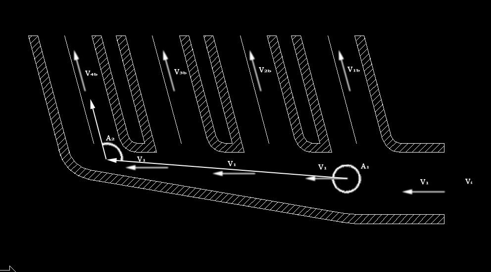
You mean something like this josh?


nothing is to scale, or the right size, but just the general design.


Edited 2 time(s). Last edited Thursday, August 27, 2009 8:45 AM
Attachments
intakemani.jpg (145k)


PRND321 Till I DIE
Old Motor: 160whp & 152ft/lbs, 1/4 Mile 15.4 @88.2
M45 + LD9 + 4T40-E, GO GO GO

Re: My Engine design, torque monster, all imput welcome
Friday, August 28, 2009 7:26 AM
Well, it depends on what your trying to do. You can slope the plenum and divert the air towards the runner initiation, or you can slope the runner face and have part of the runners side wall 'pull' some of the air into it...if you will. In many cases the difference could be a splitting if hairs difference....until you figure on your cam profiles. This will make the deciding factor as which style of plenum cross sectional area reduction method you chose. The style you posted up is great for a cam profile that has very little intake resonance(or limited)..hot cams....meaning the intake cams are a little late to open but hold open pretty late as well(slightly after BDC). Inversely, a runner side x-sec. area reduction scheme(where the runners bite off a piece of the plenum 'per say') is better to allow the effects of reversal in the runners when your cam profiles are more sedate. Other circumstances that could help a deciding factor would be the velocities in question, but this is more driven by the runner diameter and plenum size. Since we are talking about a generally RPM limited motor, I'd probly lean towards a mix of the two in all honesty. Step the runners just a tad and the plenum mostly like above in your drawing...slight cone shape with a little lower runner initiation angle. Also, try running a helm resonance calc to tune the runner length....and use that length as your target "effective length" factoring in the elbows and such as adding to your 'equivalent length' runners. ie: a 90 degree elbow bend gives a pressure drop equal to X length of straight pipe.....use all straight pipe calcs to get your effective frictional losses in your runners....this is the only true way of measuring/making an equivalent length manifold(intake or exhaust). Then get an estimate of your fouling and such and then use Bernoulli's(sp?...dont want to look it up) equation to get your total pressure drop in each runner.....then match these #'s...excel will be your friend. "Try" to see if you can match the pressure drop all the way from the TB to the intake valve for each runner....you'll find that once you have doen this...your plenum dimensions will be generated as you do it since to get the Bernoulli's equation you will need pipe diameter......or...plenum diameter...but remember, you need to decide your minimum plenum diamter too to keep your total displacement between 1.0-2.0x your engine displacement....so, you can't let this run the show...but you can use it to compromise along the way as a check during your design.

I hope this all helps....probly confusing...and it really is. You think your doing something right, but the things you will forget along the way will suffer and such....there's not two sides to this coin....there's a million sides and they all want attention. You'll find out quickly there will be limitations the can't be avoided and you will then be making the 'best' design you can with the previous limitation. This is actually a good thing, limiting some variables is the first thing you want to do.


"Never argue with an idiot. They'll drag you down to their level, then beat you with experience!" -Anonymous

Re: My Engine design, torque monster, all imput welcome
Friday, August 28, 2009 7:44 AM
I took your quick drawing and added some variables to it where they should be calc'd at. This is not all of them, but a good start at least.


Dammit....The V's in the plenum should read from left to right, V4,V3,V2,V1,Vi...sorry...must have hit the undo button a few times on accident. Also, Vi is pre-TB, V1 is post TB plate.

EDIT: the ultimate goal would be to have Vxb's all equal(pretty much a function of the engine so...not much to influence, except for runner diameter, which is pretty much to only thing your going to change here other than routing to adjust the velocity in an effort to help match the plenum velocity) and have your Vx's equal each other and a reasonable percentage of your Vxb's. Hugely a function of plenum size/design. This is where an intake can be good or bad. Don't worry about thinking outside of the box a little bit. I've seen good intakes on FSAE cars that have a good plenum velocity and a .75" pipe fitting off the bottom of the plenum to a friggin tank that gave the intake the volume needed for good throttle response. Thinking out of the box tho can cost you. Materials and dyno time add up, this is the primary reason why you see most market and after-market designs stick to a limited number of design concepts. Cause they 'work' and generally have a long history of 'working', and of the norm as far as looks in the industry. But, might not be optimal, but cost plays a big roll...this is why I ask how do you really want to go with it.


Edited 4 time(s). Last edited Friday, August 28, 2009 10:16 AM

"Never argue with an idiot. They'll drag you down to their level, then beat you with experience!" -Anonymous
Re: My Engine design, torque monster, all imput welcome
Wednesday, June 01, 2011 7:29 AM
This might actually surprise people, but I'm actually working on my cavalier again. I need to make a post in the photos and media forum. Maybe this weekend I can bring my camera with me when I work on my car.

Engine Tentative build list...Not is stone yet

Intake to false headlight housing for when I drag race.
Some crap intake from head light housing to TB
56mm 2.4 TB, with LG0 butterfly plate
LD9 intake manifold opening bored for smother airflow
96-98 LD9 Head, Head Casting number is 683-18, mild port job, LG0 Valves
87-88? quad4 Steel lined Cam Towers
HO or Larger Reground Cams, 2nd Design Quad 4 Lifters, & LG0 Springs
Possible McMoney Power Steering relocate to old A/C condenser location, or gutted rack with looped lines.

99-02 Block with oil passages bored and chamfered
Wisco 10:1 Pistons, 0.060" Over Bore
2.3 oil pump conversion using Brads method, with stock oil pan, adapter block, and oil pump pickup
Eagle H-Beam Rods
4-1 Rons Long Tube Header, rather have a 4-2-1, but can not find one I like.
2.5" exhaust with cutout in tunnel
Stockish quiet muffler

My current pulleys or a special LG0 diameter crank pulley
Stock lightened flex plate


I'm sure I forgot a lot.


PRND321 Till I DIE
Old Motor: 160whp & 152ft/lbs, 1/4 Mile 15.4 @88.2
M45 + LD9 + 4T40-E, GO GO GO

Re: My Engine design, torque monster, all imput welcome
Wednesday, June 01, 2011 7:36 AM
stock lightened flex plate?


Re: My Engine design, torque monster, all imput welcome
Wednesday, June 01, 2011 8:55 AM
Ill be keeping an eye on this. stalking these forums is so educational! Good luck on the build man!
Forum Post / Reply
You must log in before you can post or reply to messages.


Start New Topic Advanced Search